Solar Dump Mode Controller
In the solar and wind generation area, people talk about Dump Mode
Controllers. What this really means is that you bring the batteries
up to a certain level of charge and then dump the remaining power into
some other load. One of the more common loads is a 12 Volt hot water
heater. In this situation you top off the batteries and then heat
water until the solar or wind stops. The controller then resets back
to the first battery.
The RV problem is that you want to charge your house battery and your
engine battery as both get discharged by different electrical loads
while you are dry camping. In my case I added a third battery which
was going to be used during cloudy weather to replace my house
battery. This battery was actually in a battery box that was not
connected in any way to the RT. We had very good weather this year in
Baja. The battery only got used to start a friends pickup when his
battery went bad and to recharge the laptop battery through a small
inverter a few times.
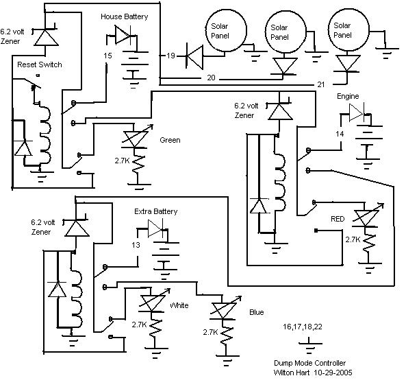
Below you will find a diagram of the controller showing 3 solar panels
and 3 relays. The numbers refer to a connector that was placed along the edge
of the circuit board. The zener diodes are listed as 6.2 volts but 6.6
would work better. The trip point for each relay is the pull in voltage
of the relay plus the zener voltage. The battery sees one diode drop less.
My relays pulled
in at 8 volts so add 6.2 and you get 14.2 but the battery is only seeing
about 13.5
volts. Some people say it should be just a little higher than that so a
zener voltage of 6.6 would work also.
The diodes that are in series with each battery
must be large enough to handle the full charging current. The reset switch forces the controller back to
battery number one.
The size of the relays would depend on how much total current you
planned to supply. In my case 5 amps was enough so I used some small
relays. The current to run the relays comes from the solar panel and
not from the battery.
I added 3 LEDs so I could tell which battery was being charged. This
made understanding what was going on a lot easier. Each one was a different
color. Green was battery number 1, red was battery number 2, and white
was battery number 3. Blue meant that all the batteries were full.
There are two down sides to this type of controller. Once the
controller has moved to the second or third battery, someone could
come and discharge the first battery and it would not get any more
charge until the next day when the controller starts over. To solve
this problem I added a switch which reset the controller to the first
battery. Sometimes we were onto the second battery before lunch and
we wanted to use some electricity to make lunch. After lunch I would
hit the switch and let it start over on the first battery.
The second disadvatage is that a pulse width modulated controller can
probably get 5% to 10% more charge into a battery than a on/off type
controller. The downside of these controllers is when your battery
gets all the way up, the rest of the power is wasted. I decided to
save the wasted power and not worry about the last 5% to 10%. This is
a trade off that works for me but might not work for everyone.
Back