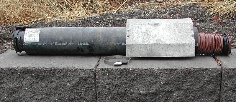
The first step was to remove the brown (blue) hose and its holder. Notice the heat shield made of tin, which protects the PVC pipe from the exhaust pipe.
The fitting that the hose connected to was glued into the 3-inch pipe that came from the valves. I removed the 3-inch pipe from the RT and made several cuts on the inside of the fitting with a reciprocating saw. I was then able to break the glue with a screwdriver and remove the fitting. After a little sand paper work the plastic pipe was ready to accept a new piece of 3-inch pipe. Here is the layout. The three-inch pipe was then reduced to 1-½ inches using a rubber reducer. The 1-½ inch pipe was then connected to the pump using another rubber connecter and clamps.
The output of the pump has a 1 inch barbed connector and I used a matching barbed connector and hose, which went into a elbow.
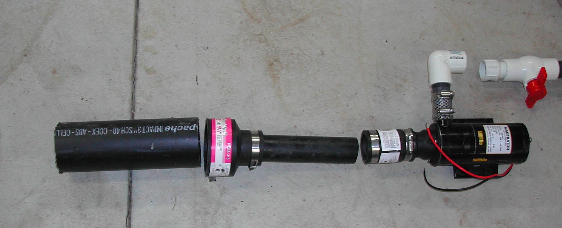
I chose a Shurflow pump, which cost less than a hundred dollars. By removing the two screws at the back of the motor, the output can be changed from one side to the other. This was necessary to make the output come out on the top when installed into a 1996 190 Popular.
I added a valve on the output because I have seen the other two valves leak one too many times. If this happens again I will shut off the valve on the output until I choose to work on the slide valves.
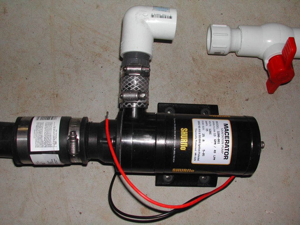
The new hose also has a valve on it. This allows you to seal the hose if you are dumping to a high location. I chose to use a plastic union as my connection. We will see how well this works. The union gives you a full 1-inch connection as compared to a garden hose, which often ends up being only ¾ of an inch.

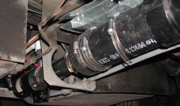
A heat shield was made to protect the 3-inch PVC from the exhaust pipe.
Here is what it looks like connected to the pipe. It is just some sheet metal, which is connected together with pop rivets.
A steel mount was created from some square tubing and two pieces of ¼ inch plate.
The plate was drilled to match the mounting plate on the pump.

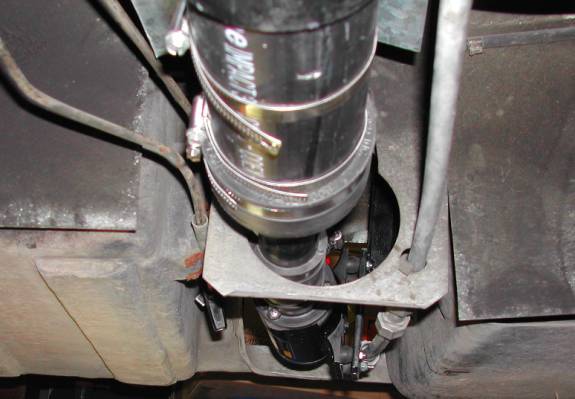
Now lets look at what all this looks like when it is installed.
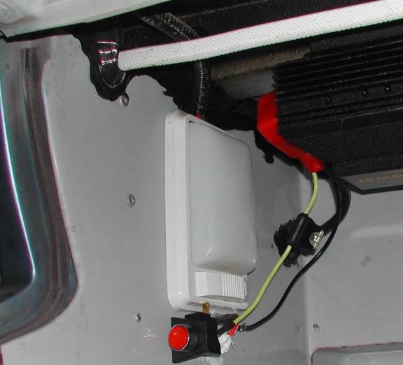
Now lets look at the electrical switch and connections. Since I have a 1000-watt inverter installed in the top of the side cabinet, I decided to connect the pump to that. It is connected to the motor battery. An in line fuse was added for protection and a 15 AMP momentary switch.
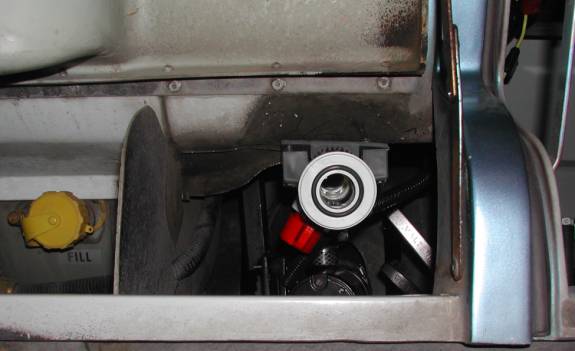
Here is one last shot of the pump with the protective cover over the wire.
I have pumped several tanks full of water through this so far and it seems to work well. The output of the pump has threads as well as a barb. The 11/2-inch rubber hose connector did not clamp tight on the barb but it did go tight over the threads. I found that you needed to add Teflon tape over the threads to keep if from leaking.
Back