The following information was made in trouble shooting the converter on my 1996 Roadtrek.
The Magnetek 6332 removal requires that 4 screws be taken out of the front panel and then 4 more removed out of the wood. Two more screws are removed to take the AC cover off the top left corner. The lower power supply portion can then be removed by taking out 4 more screws and disconnecting the 2 AC wires plus 3 DC wires.
There are really three sections to this converter. A picture should help explain what does what.
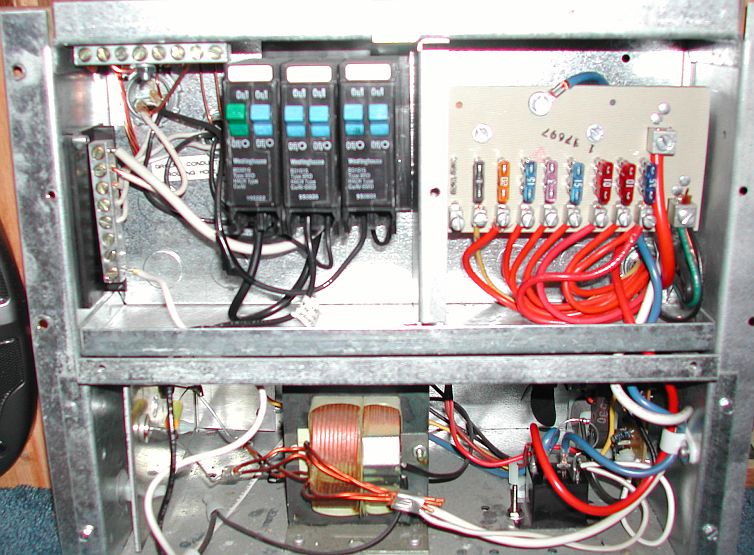
The top left corner is and AC electrical panel similar to what you would find in any house. Here is the list of what loads
they supply:
1. Main 30 Amps (Green)
2. 15 Amp Air Conditioner
3. 15 Amp Battery Charger
4. 15 Amp Side Door and Lounge Seat Receptacle
5. 15 Amp Microwave Oven
6. 15 Amp Fridge
The right top corner is a DC fuse panel. In this model the first 6 fuse locations are connected to the unregulated DC when
shore power is turned on. Some people call these unfiltered. That means there will be AC ripple on the DC so these should
not be used to power loads which are sensitive to AC. A good example would be the TV or audio system. You might hear
hum in the speakers if an audio system was connected to these fuses. Here is a list of what they are connected to:
1. Blank (No fuse installed)
2. 1 Amp CO Detector
3. 20 Amps Lights, Furnace, Hood Fan
4. 15 Amp Water Heater
5. 1 Amp LP Detector
6. 15 Amps Fridge
7. 10 Amps Roof Fan
8. 10 Amps Water Pump
9. 15 Amps TV
If you are interested in exactly how much each appliance draws, take a look at the Solar on the Cheap web page.
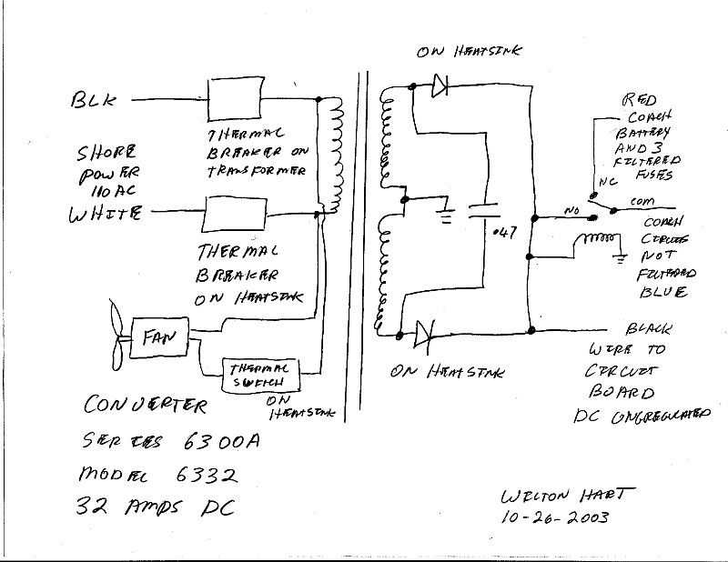
The lower section is a 32 Amp DC power supply. A block diagram is shown to help understand how this thing works.
The DC fuse panel is broken into two pieces and called Unregulated and Regulated.
I have broken the wiring diagram into two drawings so they fit better on one page. The first drawing shows the
transformer, relay and temperature controlled fan. The relay is needed to connect the ungegulated fuses to the battery
when no shore power is present. The fan comes on when the heatsink reaches a certain temperature.
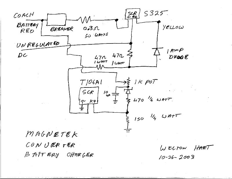
The maximum voltage shut off circuit in this power supply does not take very many parts but the theory on how it works is
not straight forward. It would not be done this way today. That is probably why it is no longer made. In general they use
one SCR to control the gate of another SCR. When the battery voltage reaches a set point, chosen by the pot, the first
SCR shuts off the second SCR and no more power is sent to the battery.
With a little trouble shooting almost any part of this converter could be replaced so fixing the unit is very possible. The one
exception would be the transformer. If it dies then the unit should be replaced.
Back